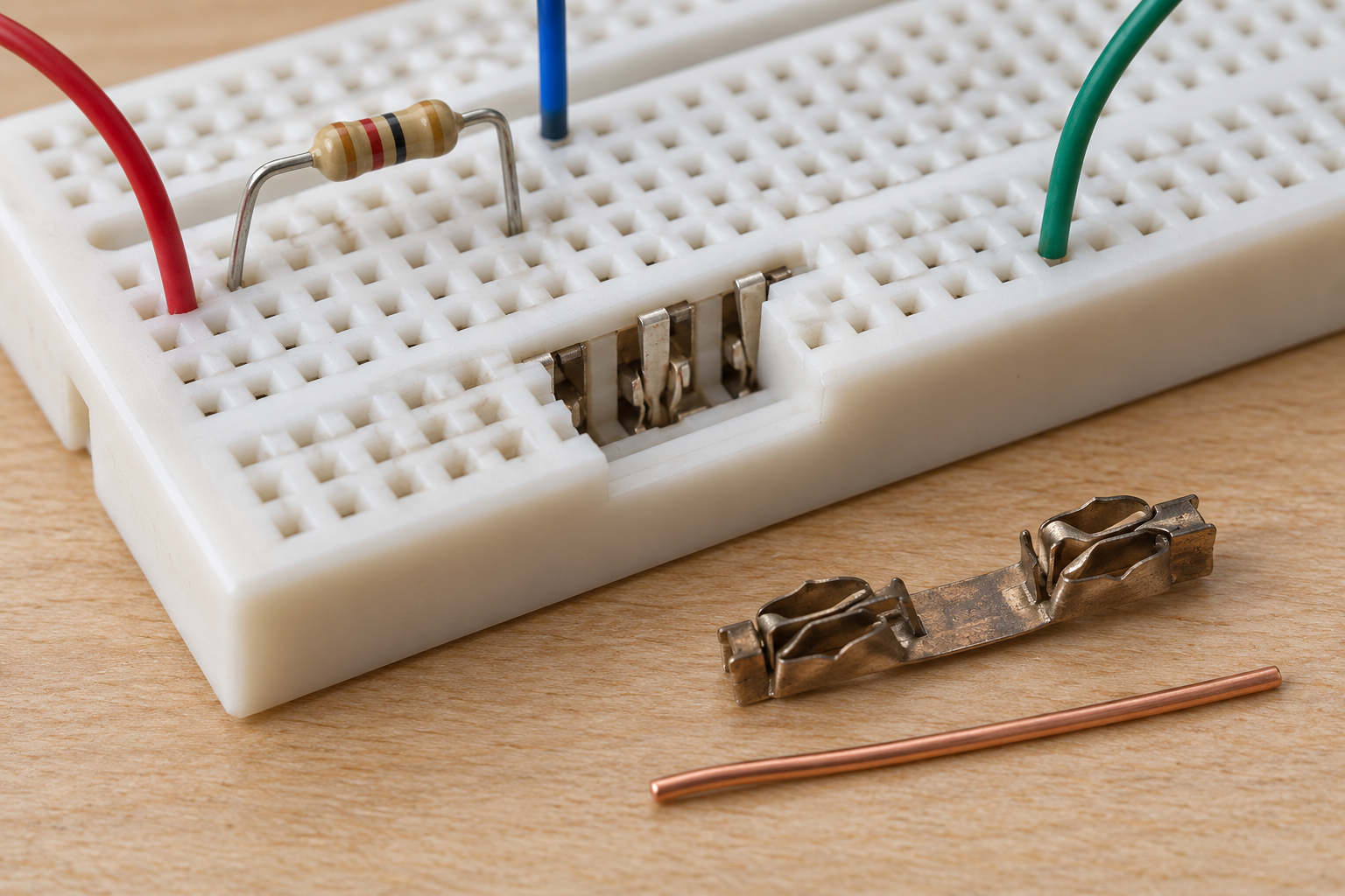
A jumper wire disappears into a neat white hole. Below the plastic, it meets a spring contact that must grip hard enough to hold the wire and conduct through it. That small meeting place is part of the circuit. The breadboard drawing may show a continuous node, but the current still has to cross each wire-to-clip joint on its way across the board. If a joint becomes loose or dirty, it can act like an unwanted series resistor—or briefly like an open switch.
This is easy to miss because the strip of metal beneath a row looks so substantial. In Adafruit's illustrated breadboard teardown, each familiar group of five holes leads to one metal clip with five gripping points. The power strips run along the edge. A circuit that goes from a supply rail, through a jumper, into a component row and back through another rail has several separate contacts, even though the schematic draws only wires. Contact resistance is the resistance of those interfaces, added to the resistance of the metal strip and the jumpers themselves. It is not one fixed resistor built into every breadboard.
Where metal actually meets metal
Two metal surfaces do not touch over every square millimetre that appears to be pressed together. Their microscopic high points make the real electrical contact. ABB's account of electrical contacts calls these discrete points a-spots and notes that surface films can further reduce the area that conducts. ABB was discussing contacts in industrial equipment, not measuring a solderless breadboard. The surface principle explains why the spring's pressure, the condition of a component lead and the contact finish matter more than the size of the hole above them.
The materials are chosen to make a reusable joint. BusBoard's BB830 datasheet specifies nickel-plated phosphor-bronze contacts and a 21–26 AWG wire insertion range for that model. It rates the BB830 at 36 volts and 2 amps, and lists a 50,000-insertion contact rating. Those figures describe that product under its stated conditions; they do not establish the resistance of a particular worn hole or a safe rating for an unmarked board. A wire far thinner than the specified range may fail to press the spring firmly. Forcing an oversized lead can deform it. The board can accept many rearrangements, but its contacts are mechanical parts with dimensions and wear.
Electrical-connector makers measure this mechanical uncertainty. For its separate SL connector family, Molex specifies an initial low-level contact-resistance test and checks the change after mating cycles, vibration and fretting exposure. Its milliohm limits belong to those connectors, not to a BB830. The useful lesson is in the tests: a contact's resistance has a starting value and can change when its mating surfaces move or age. The breadboard maker's insertion rating cannot tell you the state of the one socket that has held a thick pin, a thin jumper and a dozen different projects.
When the extra resistance matters
An added fraction of an ohm has different consequences in different circuits. At a tiny current through a large resistor, it may be swamped by the resistor and the meter's own uncertainty. In a supply path carrying more current, the voltage lost across the unwanted resistance grows with current. Imagine, only as arithmetic, a complete jumper-and-contact path that adds 0.1 ohm while a load draws 0.5 ampere. The drop is 0.05 volt, and the path dissipates 0.025 watt. Neither number is a measured breadboard value. They show why a circuit can read the expected supply voltage when nearly idle and a lower voltage at the device when the load turns on.
The variable case is more maddening. A lead that barely meets its clip can work while the board is still, then change when a wire is nudged. Adafruit's breadboard guide describes aging clips that lose their grip and suggests moving a suspect circuit to another section. A power rail with one poor contact may make several downstream parts look faulty at once; a bad contact on one signal row may mimic a failed component. Those are diagnostic possibilities, not a claim that every flicker, reset or noisy reading has the same cause.
The distinction matters because the breadboard hides other electrical features as well. Analog Devices' guide to breadboarding describes the resistance, inductance and capacitance added by pins, sockets and jumpers, and the absence of a ground plane. In a separate breadboard coupling lab, Analog Devices has students measure capacitance between adjacent metal strips. A high-speed waveform can ring or couple into a nearby row even when every DC contact is sound. Conversely, a poor DC connection is not cured by rearranging a fast signal trace. The circuit's symptom and the conditions that provoke it should guide the search.
There is also a simpler trap: sometimes the supposed conductor is not continuous at all. Adafruit's rail-layout notes warn that the rails on opposite sides are separate and that some long rails break at the middle. A missing bridge across that break is an open circuit by design, not a high-resistance spring. Before diagnosing a subtle contact, establish which holes the board actually joins. The colored lines are hints; a continuity check of an unpowered, empty board can confirm its layout.
Test the path under the conditions that fail
Start with the physical route from source to load and back. Mark every inserted lead and jumper along it. Check that each wire fits the board's specified range, is fully seated and has an undamaged straight end. Substitute a known-good solid jumper, then move a suspect connection to a fresh row. Change one thing at a time. If the fault follows a wire, that wire is implicated; if it remains with one socket, the socket deserves attention. If neither change helps, the investigation moves on.
A voltage reading under load can tell more than a quick continuity beep. With an appropriate low-voltage circuit powered normally, measure at the supply output and then at the device's power and return points while the load is doing the thing that causes trouble. Measure across successive segments of a supposedly continuous power or ground path to locate where voltage is being lost. A significant difference reveals a resistive path, though it may include wire, clip and probe contacts together. Keep probe tips steady; a probe is another temporary metal contact. Do not use an ohms setting on a powered circuit.
For a genuinely small resistance, a two-wire meter reading includes its leads and their contacts as well as the joint under test. National Instruments' resistance-measurement guidance, published in 2023, recommends a four-wire arrangement when precision requires separating the current-carrying leads from the voltage-sensing pair. That is a measurement method, not a demand that every hobbyist buy a laboratory meter. On an ordinary breadboard, comparing voltage drops while current flows and swapping one suspect connection often answers the practical question sooner than chasing an absolute milliohm figure.
The board remains valuable precisely because it lets a circuit change in minutes. Its spring contacts are the price of that freedom. For a low-speed experiment with forgiving tolerances, the extra joints may be inconsequential. For a precise low-resistance measurement, a sensitive analog input, a fast edge or a build expected to survive vibration and time, the joints become part of the design decision. Analog Devices points to soldered prototypes when performance demands it, and BusBoard offers a solderable board with the BB830 pattern for work that needs a more permanent connection. A good breadboard test establishes what the circuit can do. It should also tell you which connections you still need to trust.

A thought worth keeping?